
Hello There!
See your building as a living 3D twin you own.
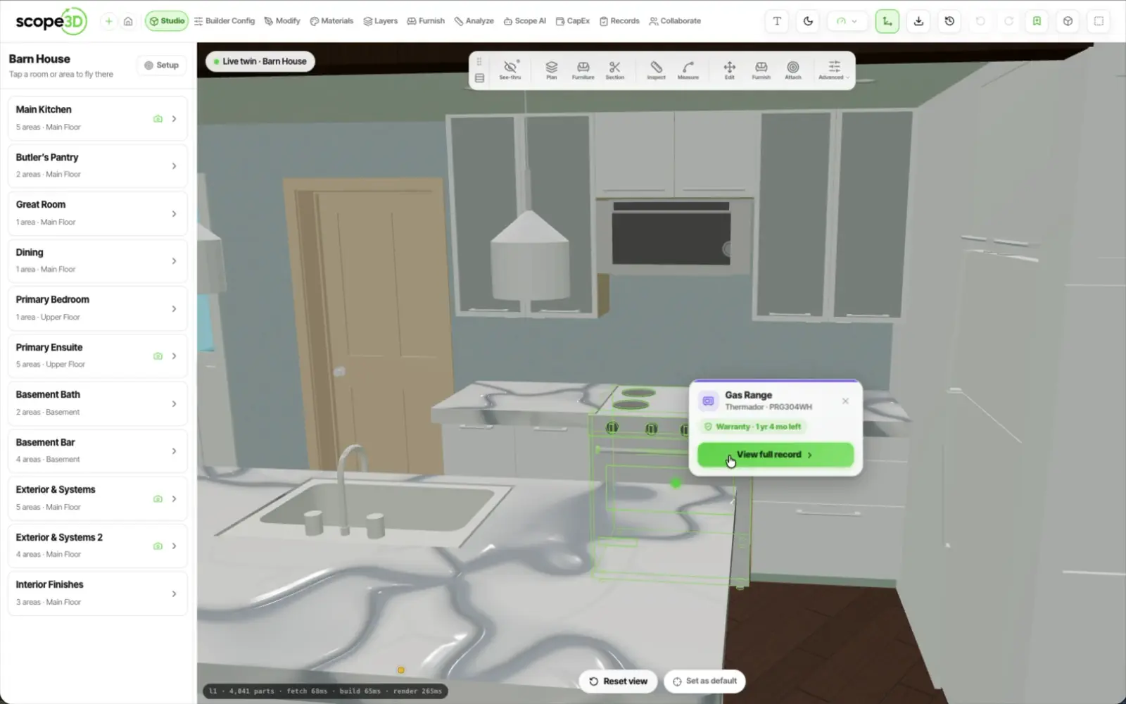
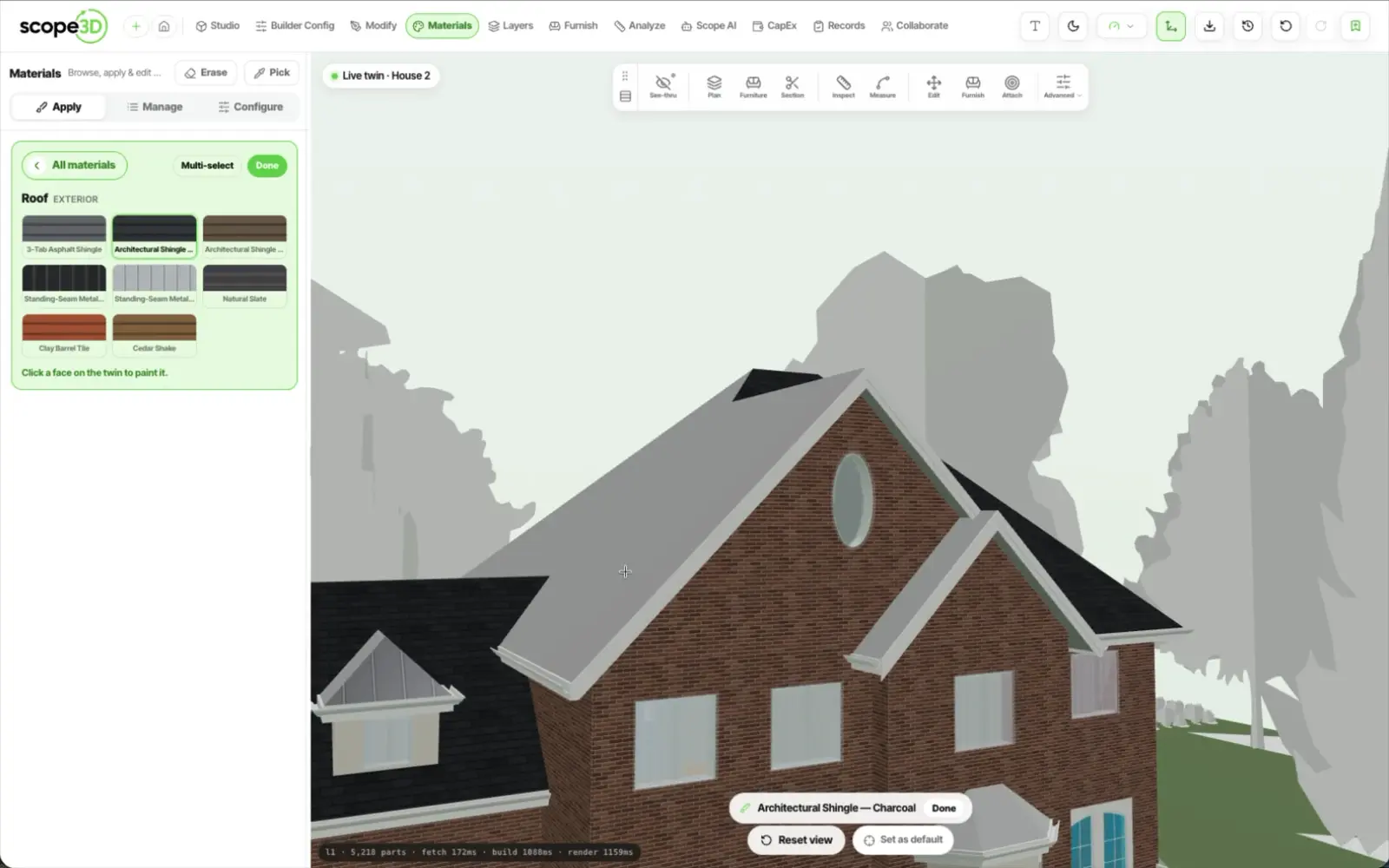
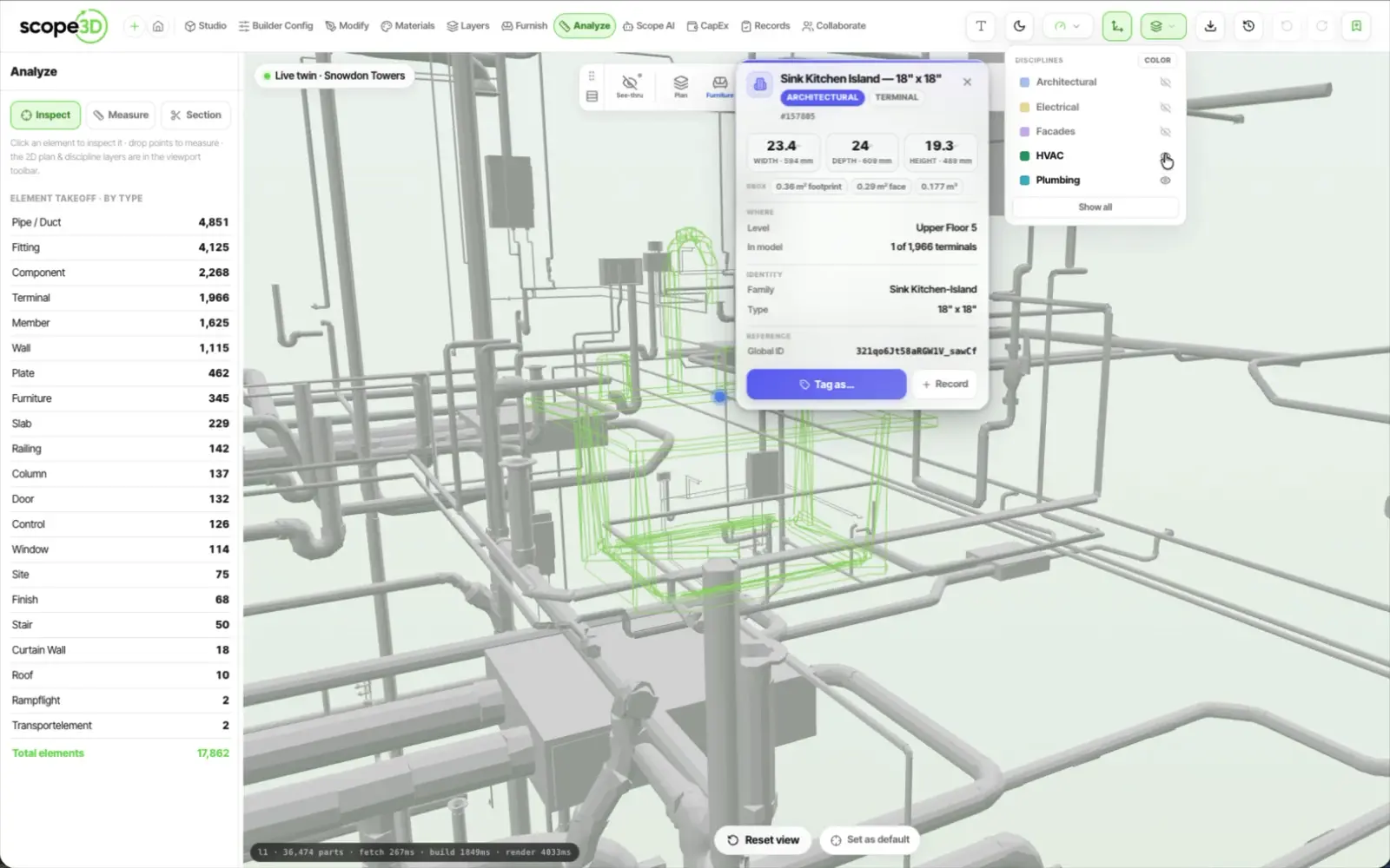
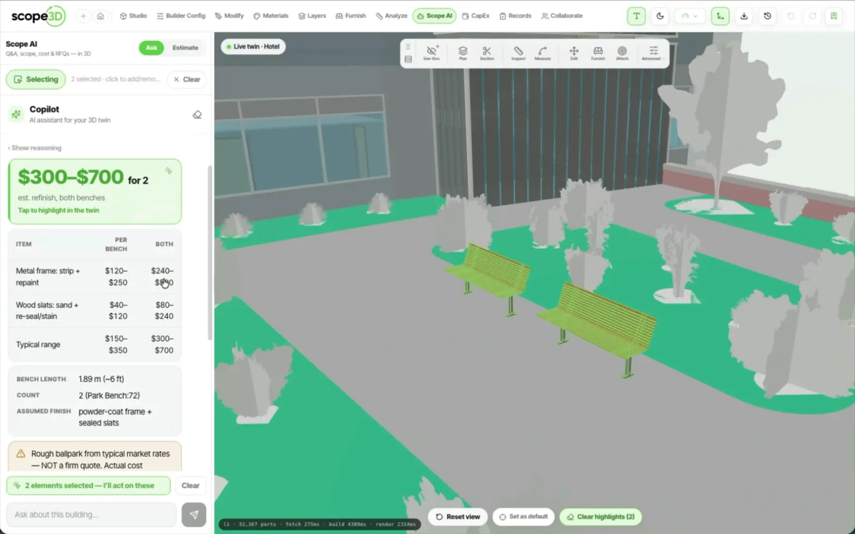
Hello There!
See your building as a living 3D twin you own.
The plan leaves as a file someone else can open, or as paper.
Vector out, at the scale it was drawn. Lines stay lines, so it can be dropped into a report or marked up without going soft.
The same cut as CAD geometry, so the consultant who asked for a plan gets one they can work in rather than a picture of one.
Title block, dimension chains and space areas on the sheet, so what comes off the printer is the drawing and not a browser window.
One chip over the 3D twin, and what you set stays set for that building.
A live slice on X, Y or Z, dragged as a fraction of the building rather than typed as a coordinate. The cut is saved against the property, so it is still there when you come back tomorrow.
Show one storey and drop the rest. The press cycles through three states rather than toggling two, so every press changes something you can see. On a single-storey model the control is hidden instead of doing nothing.
Set the pose the building opens in: which storey, which cut, what is hidden. Everyone who opens the twin after that lands on the same view.
What else the twin reportsMeasure and the surface-region tool run the same area maths, deliberately, so one drawn shape cannot read 4.10 m² in one tool and 4.06 m² in another.
An open-plan ground floor is one slab in the model and four rooms in the building. Draw the rooms on the overhead plan and the twin can hold both readings at once.
Each area you draw is a shape with a number attached, which is what makes it a quantity later rather than a note.
Draw it on the overhead plan
A polygon, a name, and its own floor finish.
One slab, several room floors
The finish renders as a patch clipped to the polygon and sat over the shared slab, so tile in the kitchen and oak in the living room live on the same piece of geometry.
Each area carries its own m²
Measured off the shape you drew, by the same maths the measure tool uses.
They roll up into the takeoff
So the flooring line in an estimate is a measurement of the room, not a guess at how much of the slab it covers.
Open a twin, drag the plane through it, and take the drawing away as SVG, DXF or paper.